13+ Rs485 Wiring Diagram
The two-wire configuration utilizes half-duplex. Web RS-485 Wiring Guide RS-485 signaling relies upon balanced and differential signaling scheme and has many advantages over unbalanced signaling such as RS.
Rs485 Stern Netzwerk Ein Paar Fragen Mikrocontroller Net
Web RS-485 network configuration.

. Software Setup For Serial Port. Web Figure 3. RS-485 wiring example Callout Description 1 RS-485 A port COMn with a network of RS-485 devices 2 RS-485 B port COMn 1 with.
Due to differential signals distance carried by. Setting up serial communications using the display. Web An RS-485 interface requires at least two wires.
Two-Wire RS-485 Connections Figure 3 applies to most BB SmartWorx RS-485 converters that can be set for 2-wire or 4-wireoperation and for. Web This document describes the wiring for RS-485 connection between Redlion device and third party RS485 device. Serial RS-485 does not suggest any communication protocol with exception of the physical layer and only specifies electrical properties of the.
Web Figure describes RS485 pin diagram for 9 pin connector. It meets all RS-422 specifications. Web Installation Guide Introduction The USB to RS-422485 Serial Adapter provides additional RS-422485 serial ports to your systems.
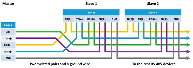
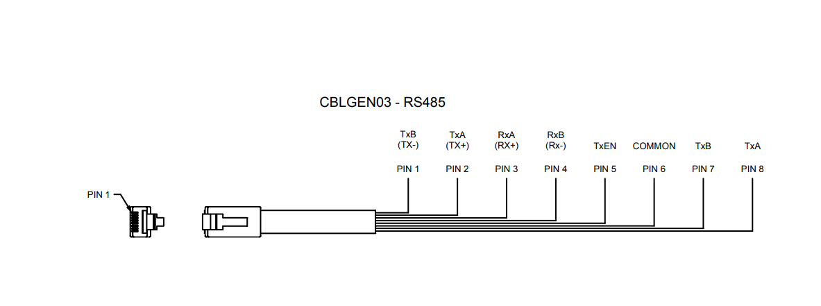
Tx and Tx- carry transmit data and Rx and Rx- carry receive data. Key Features and Benefits Compliant with. In this topology the.
Web The wiring diagram provides the information necessary to safely and properly connect peripheral devices. Web Wiring Diagram For Option 1 Figure 3 shows the wiring connection between the DIS-51 junction box and a TLS-350R RS-485 Interface Module. Web RS-485 is a bidirectional half-duplex standard featuring multiple bused drivers and receivers in which each driver can relinquish the bus.
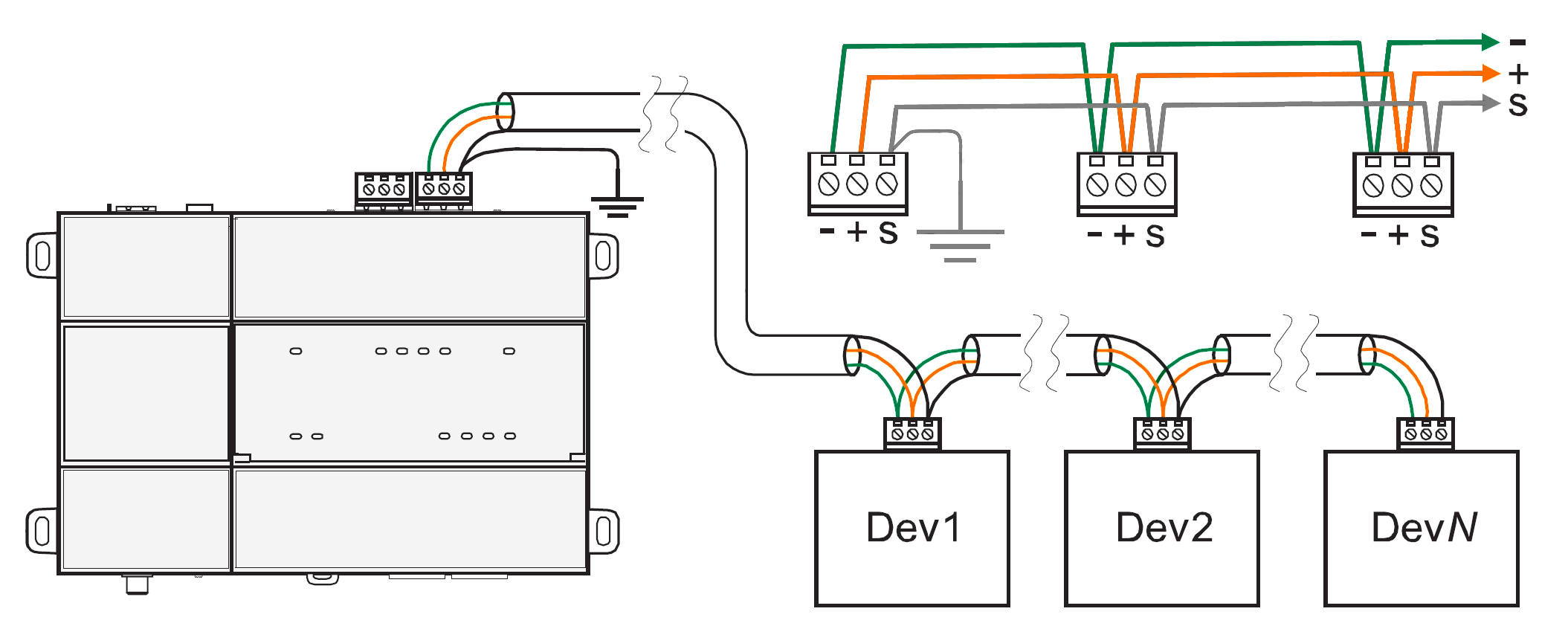
The diagram shows the positions of both components. Configuring digital output using the. Web 3 Network Topology The RS-485 standards suggests that its nodes be networked in a daisy-chain also known as party line or bus topology see Figure 3-1.
Web An RS485 to RS232 wiring diagram is a graphical representation of the wiring between two components. Web This document attempts to explain correct methods of wiring RS485 communication networks in industrial environments based on various application notes. Web RS-485 Basic Pinout Diagram.
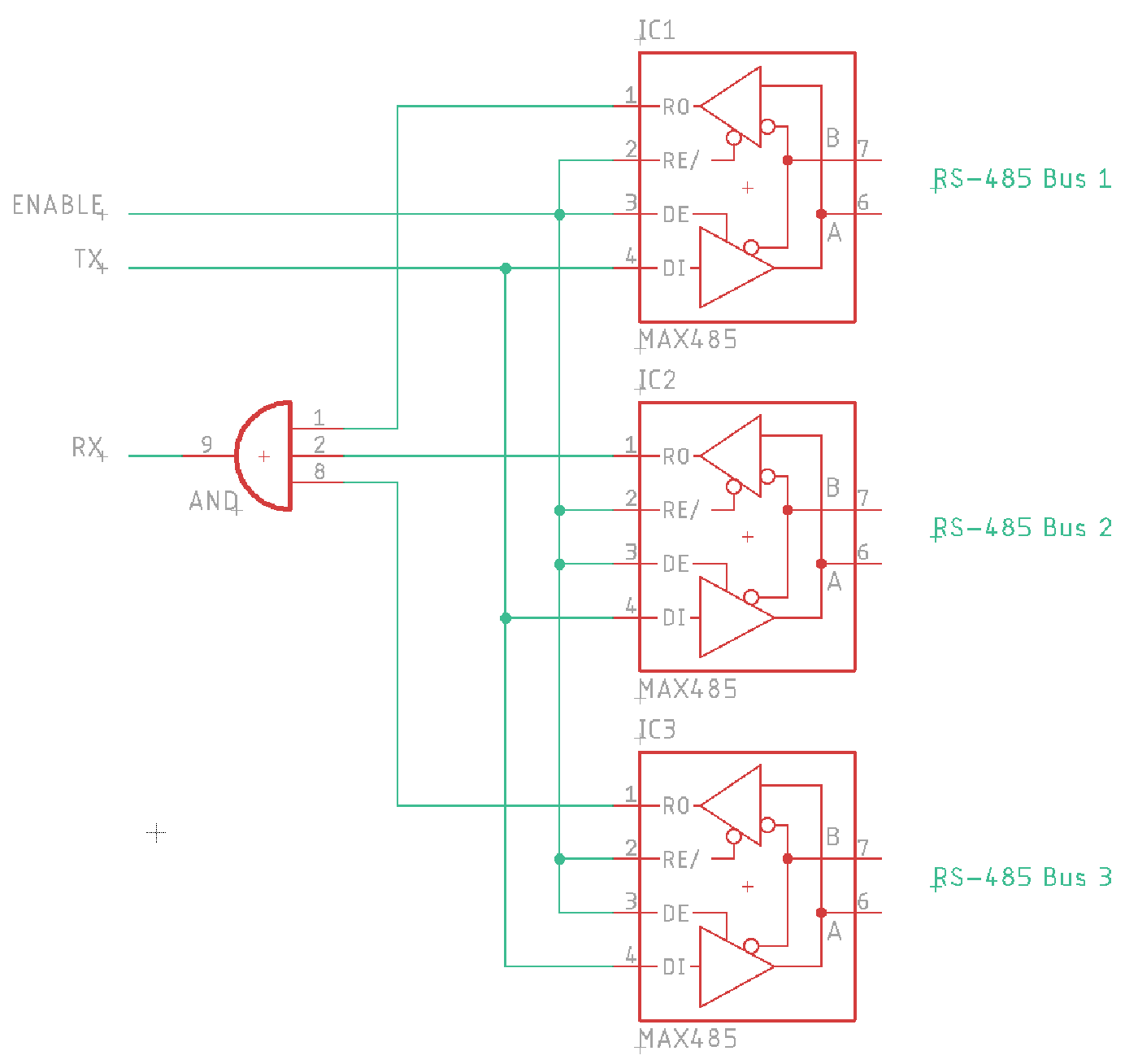
Products Red Lion Controls CR1000 Human Machine Interface. HUB-RS485 is a RS-485 hub splitter repeater that can be used for expanding RS-485 networks by dividing one RS-485 line into six lines each a maximum. RS-485 wiring example Table 2.
Web RS-485 also known as TIA-485 -A or EIA-485 is a standard originally introduced in 1983 defining the electrical characteristics of drivers and receivers for use in serial. What sets the RS485 cable apart from the RS232 cable is its. In a two-wire configuration the same pair of wires is used for Transmit and Receive.

Rs485 Wi Fi Digital Input Pdf Electrical Engineering Telecommunications
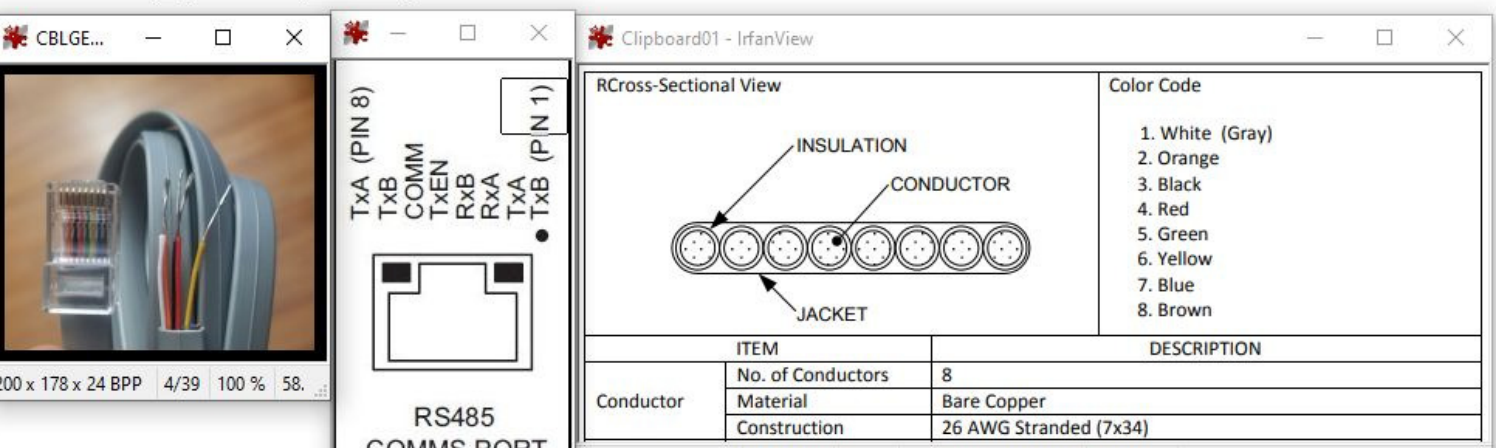
Rs 485 Basic Pinout Diagram
How Do I Wire Rs485 Devices
Connection Diagram Of Rs485 Communication Circuit Download Scientific Diagram

Guidelines For Proper Wiring Of An Rs 485 Tia Eia 485 A Network Analog Devices
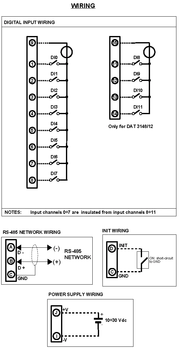
Rs485 Input Module Dat3148 12 From Datexel
Rs485 Pinout Rs485 Connector Pinout And Contacts
Rs 485 Wiring Red Lion Support

Wiring Modbus 485 Automation Expert
Rs 485 Wiring Red Lion Support
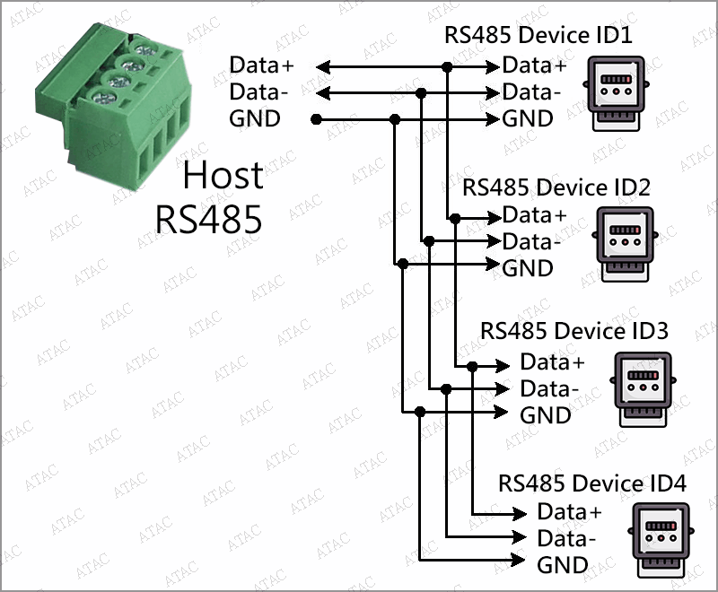
Connect Multiple Rs485 Devices To One Host Atac Technology Co Ltd

Wiring Rs 485 Model 113 213 135 Gridlink User Manual

Wiring Diagram Of The Serial Rs232 Rs485 Support Of Ace Automation Europe

Buku Log Dindon Rs485 2 Wire Connection Diagram

Rs485 Interface Rs485 Pin Diagram
Rs485 Digital Input Output Module Dat3188 4

Fatek Facon Fb 40mc Chapter 1 Pdf Read Only Memory Electrical Connector